Lenel S2 LNL-1324E Network-Connected Door I/O Module
Description
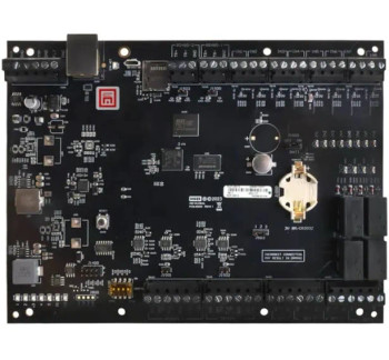
Lenel S2 LNL-1324E Network-Connected Door I/O Module (LNL-1324E)
The LNL-1324E is a flexible network-wired hardware module that interfaces readers with Open Supervised Device Protocol (OSDP) for two doors; or acts as an alarm panel (I/O points) to the OnGuard system (version 7.6 or higher).
The LNL-1324E module allows doors or auxiliary I/O to be conveniently wired to an OnGuard system using structured cabling and Ethernet, rather than via dedicated RS-485 wiring. When combined with a compatible LenelS2 Intelligent System Controller, this allows either a 100% Ethernet solution or a hybrid system to be deployed, depending on the security and IT infrastructure considerations of the installation.
The LNL1324E module provides the same local I/O linking and fallback options as traditional serial-connected modules, but with the convenience and flexibility of network connection. The LNL-1324E module can be configured in one of two operating modes. When in the network-connected dual door controller mode, the LNL-1324E module allows each door to have the following configuration: one or two OSDP readers to be connected, controlling the door; one auxiliary input and one auxiliary relay output are also available, in addition to dedicated exit request and door contact inputs and a door lock output relay. And, when in the network-connected I/O module mode, the LNL-1324E module allows up to six inputs and four relay outputs to be configured using the OnGuard access control system.
Features & Functionality:
- Supports 10/100 Ethernet communications to LenelS2 X-Series Intelligent System Controllers
- Advanced Encryption Standard 256-bit encryption supported
- Mounts into a standard ANSI/NEMA triple gang switch box for a compact footprint
- Firmware stored in flash memory; background download of firmware updates supported
- Custom or standard end-of-line resistors supported
Features when in network-connected single door controller mode:
- OSDP reader port supports four OSDP reader addresses
- Paired or single reader support per door
- Supports OSDP, including biometric template transfer and Secure Channel encryption
- Two outputs; one dedicated for a strike and one general purpose (Form C, 2A @ 30Vdc) per door
- Two fixed inputs for door contact and request to exit (REX) per door
- Two programmable auxiliary inputs, one for each door
Features when in network-connected I/O module mode:
- Four general-purpose auxiliary relay outputs (Form C, 2A @ 30Vdc)
- Six programmable auxiliary inputs (supervised or unsupervised)
Detailed Specifications
| Specifications | |
|---|---|
| General | |
| Usage | The interface is for use in low voltage, Class 2 circuits only. Installation must comply with all local fire and electrical codes. |
| Primary Power | |
| PoE | 12.95 W, compliant to IEEE 802.3af |
| PoE+ | 25 W, compliant to IEEE 802.3at |
| External Power | 12 Vdc ±10%, 1.7 A maximum |
| Power Output | |
| PoE | VO (TB4-1) and RVO (TB7-4), combined: 12 Vdc @ 0.66 A |
| PoE+ / 12 Vdc | VO (TB4-1): 12 Vdc @ 1 A max, RVO (TB7-4): 12 Vdc @ 0.5 A max |
| Communication | |
| Ethernet | 10-BaseT / 100Base-TX |
| Inputs & Outputs | |
| Inputs | Six unsupervised / supervised, standard EOL: 1k/1k ohm, 1%, 1/4 watt |
| Outputs | Four relays: Form-C contacts: 2 A @ 30 Vdc resistive |
| Reader Interface | |
| Power | 12 Vdc @ 0.5 A max (RVO, TR7-4) |
| Communications | 2-Wire RS-485, OSDP™ protocol, four devices max |
| Cable Requirements | |
| External Input Power | 1 twisted pair, 18 AWG (if required) |
| Communications | Ethernet, CAT-5 minimum |
| Alarm Input | 1 twisted pair per input, 30 ohms max, typically 22 AWG @ 1000 ft (304.8 m) |
| Relay Outputs | As required for the load |
| Reader Data & Power* |
RS-485/power: 2 twisted pair with shield, 24 AWG, 120 ohm impedance, 4000 ft (1220m) max Or RS-485: 1 twisted pair with shield, 24 AWG, 120 ohm impedance, 4000 ft (1220m) max Power: 1 pair 18 AWG* *Type of cable(s) and gauge determined by length and voltage/current requirements. Local power source may be required. |
| Mechanical | |
| Dimensions (W x L x H) | 5.5 x 2.75 x 0.96 in. (140 x 70 x 24 mm) without bracket 5.5 x 3.63 x 1.33 in. (140 x 92 x 34 mm) with bracket |
| Weight | 4.0 oz. (112 g) without bracket 5.0 oz. (142 g) with bracket |
| Environmental | |
| Temperature | -55 to 85°C storage, 0 to 70°C operating |
| Humidity | 5 to 95% RHNC |
| Heat Output | 8.2 BTU/hr @ 12 Vdc |
| Approvals | |
| Certifications | FCC Part 15, CE, RoHS, UL 294, UL 1076, CAN/ULC 60839-11-1:2016, CSA C22.2 No. 205-1983, cUL/ORD-C1076 |
| Parts and Spare Parts | |
| LNL-1324E | IP Door Interface, OSDP readers only. Two door support, max four OSDP readers. Power options: PoE, PoE+ or 12 VDC. One aux input and one aux output per door. |
| LNL-1300-TAMPER | Tamper cable for LNL-2210, LNL-X2210, LNL-1300, LNL-1330-S3, LNL-1300E, LNL-1324E |
| LNL-RPL-MTG-3G | Replacement mounting plate for LNL-2210, LNL-X2210, LNL-1300E, LNL-1324E with 4-40 screws |


